Custom BLDC motor and three‑phase drive
It passed every static check, then stalled under load. The firmware assumed four pole pairs. The rotor has three.
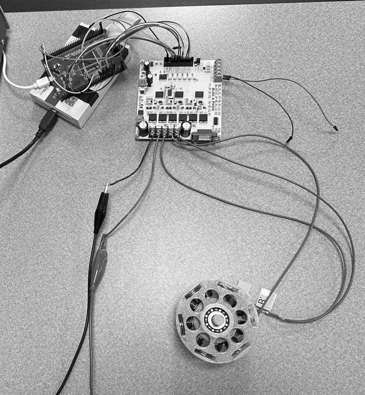
How the motor came together
- Rev 1: an Arduino and a 30 A ESC. The ESC wouldn’t arm below 3 A.
- Rev 2: a PWM module. It shorted and blew the MOSFETs.
- Rev 3: a TMS320F28377D running open-loop SPWM in C, debugged over isolated JTAG. It ran.
- Under load it fell out of step and stalled. The firmware assumed four pole pairs. The rotor has three.
- One constant, four to three. The field and the rotor lock.
Build
A 9-pole stator, hand-wound at 100 turns per coil and connected in delta. Six neodymium magnets make three pole pairs. The housing is 3D-printed PETG.
Drive
A TI TMS320F28377D dual-core DSP runs open-loop SPWM, written in Embedded C and debugged over isolated JTAG. It drives a three-phase MOSFET inverter with gate drive and current and thermal limiting.
Three revisions
- An Arduino and a 30 A ESC. The ESC wouldn’t arm below 3 A.
- A PWM module. It shorted and blew the MOSFETs.
- The DSP build. It ran.
The stall
Under load the motor stalled and oscillated. The cause was a pole-pair mismatch: the firmware assumed 4 and the motor has 3. The bug passed every static check.
Measured
Startup torque, rotor inertia, and a stall limit of about 3 A, set by the windings’ thermals.
Next
Hall sensors, then closed loop, SVPWM, and field-oriented control.