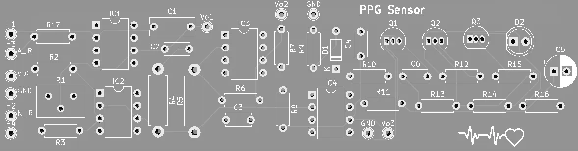
PPG heart‑rate front end and PCB
The comparator chattered because its hysteresis was too small. One resistor fixed it: R8 to 100 kΩ, a 96 mV band on the scope, and a clean output at 2.174 Hz.
How the PPG front end was fixed
- The chain: LED and photodiode, an LTC6078 transimpedance stage pulling nanoamps off a large DC bias, AC coupling, gain, a Schmitt trigger, a BJT monostable.
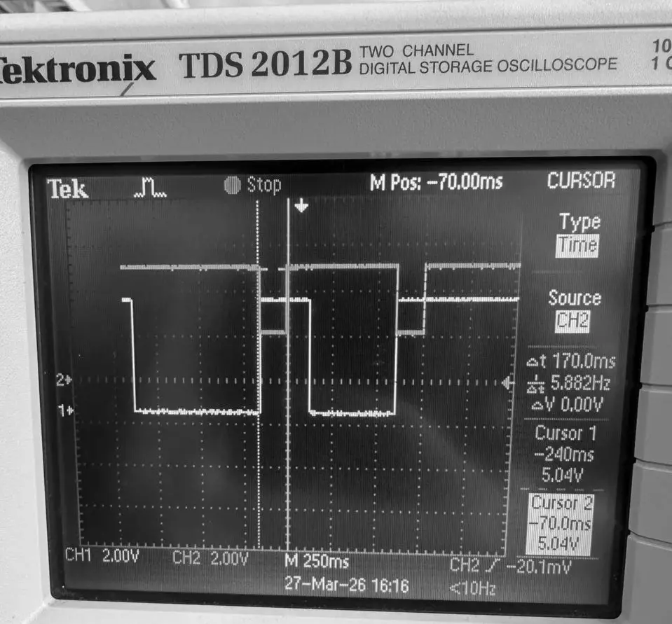
- On the scope: the photodiode signal, and a comparator that chatters every time the signal wanders across its threshold.
- Too little hysteresis, from the wrong feedback ratio. R8 to 100 kΩ gave a 96 mV band, and the output snapped clean at 2.174 Hz.
- Zoomed to 10 ms per division, the measured timing sits within ±10 ms of the LTSpice prediction.
Signal chain
An LED driver and a photodiode, then an LTC6078 transimpedance stage, about 2.1 MΩ with 10 nF, recovering nanoamp photocurrent riding on a large DC bias. After that: AC coupling, a second gain stage, a Schmitt trigger, and a BJT monostable.
The chatter
The comparator chattered at threshold. The cause was too little hysteresis from the wrong feedback ratio. I changed R8 to 100 kΩ and measured the band with scope cursors: 96 mV. The output held steady at 2.174 Hz.
Timing
Measured timing came in within ±10 ms of the LTSpice simulation.
Board
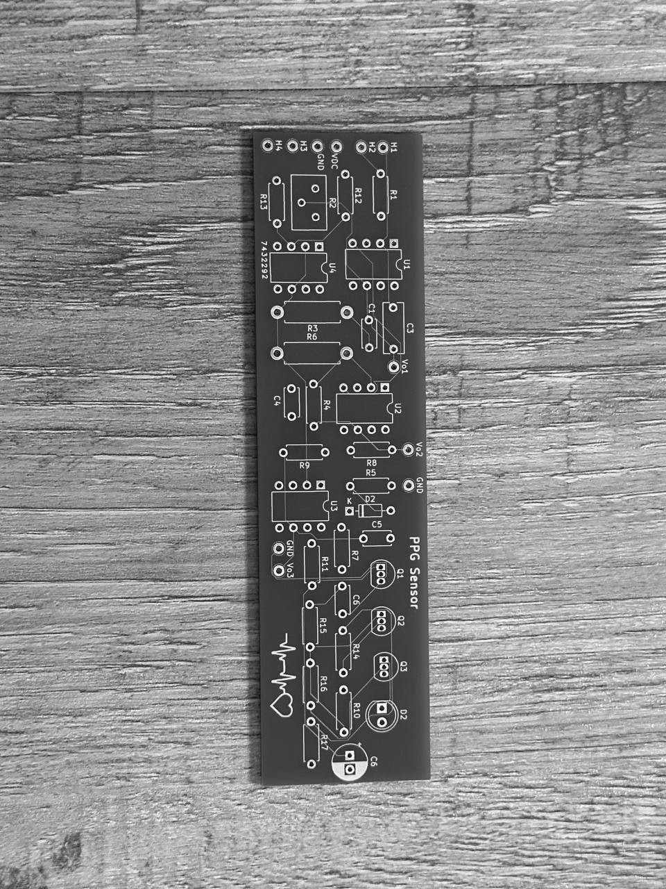
Laid out in KiCad, fabricated by JLCPCB, and verified on the bench.